Abstract
We have learned to work with the Arduino Nano to make some interesting circuits. Now lets have a look at a different type of microcontroller board the Raspberry Pi.
We will look at how a computer reads and writes analog signals, and how power is measured. Then we will put it all together.
How is Automation Possible?
I thought that before we discuss a practical application for automation using the raspberry pi, we might take a step back and look at the building blocks.
It is not alway clear how we can go from the analog world around us, to the digital world of computers. Yet this ability to convert digital to analog and analog to digital underlies much of automation.
Analog to Digital Conversion
Lets start by looking at the process of analog to digital conversion.
The green shows an analog wave, lets pretend it is a musical note, and the arrows show the measurement points, or sampling points. At each sample point, the chip or circuit, outputs a digital number representing the height of the wave at that point in time. The number of samples per second is fixed for many converters. For most music they use 44100 Hertz. This number was choosen before the first music CD were sold by Sony in 1979. If you would like more information on stampleing let me recommend Sampling (signal processing).
The numbers shown are only 4 bit values, 0-256. The higher the number of bits, the better the resolution of the sound. The standard for CDs is 16 bits, 0-65535. This allows 16 bit computers to handle the digital values as a single word. With newer chips and computers not many digital music sources are using 24 bit conversion, 0-16777215 or higher resolutions.
Additionally newer analog to digital converters can operate at higher sampling rates. Some professional equipment now operates at a 96000 Hertz sampling rate. There are even higher sample rates used for high definition audio.
Once the wave is converted into a series of numbers, we can store the numbers on any digital storage system.
Digital to Analog Conversion
Now that we see how to go from Analog to Digital, lets take a minute and discuss how to reverse the process.
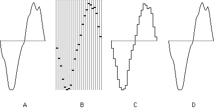
Here we can see in drawing A the original signal. After sampling the digital bits would look something like B. A straight conversion from analog to digital would produce a wave form that looked like C. But audio equipment would now handle those steps, so the sound gets filtered to look more like D.
This is the process done in you MP3 player, as well as your computer. There is some argument about the purity of the sound when converting into and out of digital.
Analog to Digital for insturmentation
Now that we understand how these converters work, what is their use in automation. The answer is that much of what we want to measure is analog. Once the analog is converted to digital, the computer is the champ at making decisions. So lets look at a few examples of using analog signals in a digital environment.
The humble thermostat
If you ever took apart a manual thermostat, you would find a mechanical analog to digital converter. Typically you have a couple wires that flex based on temperature. Then when the flex gets below a set point, it causes two contacts to close. In the same way
Washing machine
Lets look at a diagram of a washing maching from a talk I gave about micro controllers back in March of 2011.
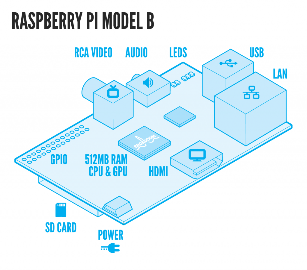
Introduction to the Raspberry Pi
Adafruit Learning the Raspberry Pi
The Raspberry Pi is a credit-card sized computer that plugs into your TV and a keyboard. It’s a capable little PC which can be used for many of the things that your desktop PC does, like spreadsheets, word-processing and games. It also plays high-definition video. We want to see it being used by kids all over the world to learn programming.
Power Monitoring
For tonights talk I thought I would discuss a circuit that you might be interested in adding to your home. This is only one project, but I thought it would give you some ideas. Besides in the process I intednd to teach you a little about electric power and how it is measured.
Before I start describing how to build a power monitor circuit, I thought we would take a side trip to understant the science behind the circuit. So we will begin with a discussion of how to measure electrical power.
Current Transformers
We need to first understand how a transformer works before we can learn how to use them.
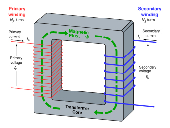
It is important to remember that transformers do not generate electrical power; they transfer electrical power from one AC circuit to another using magnetic coupling. The core of the transformer is used to provide a controlled path for the magnetic flux generated in the transformer by the current flowing through the windings, which are also known as coils.
Explaining Different Types of Transformers
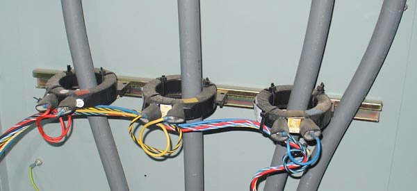
Now that we understand how a transformer works, lets examine what a current transformer is:
A current transformer has a primary coil of one or more turns of heavy wire. It is always connected in series in the circuit in which current is to be measured. The secondary coil is made up of many turns of fine wire, which must always be connected across the ammeter terminals.
A clamp-on ammeter works in a similar way. By opening the clamp and placing it around a current carrying conductor, the conductor itself acts as a single turn primary.
Explaining Different Types of Transformers
Voltage measurement
In many ways measuring voltage is much easier than measuring current. One method would be to use a transformer which steps down the voltage from 120 or 240 volts to 5 volts. After our talk about transformers above, you might think this the only way to do it.
But another method would be to use a voltage divider set of resistors. This allows you to select the output voltage by selecting the correct resistors. Lets have a look at such a circuit.
So lets do the math for 120 volts input and say 4.8 volts output. I will choose R1 = 1000 Ohms, so then R2 = 24000 Ohms.
Putting Voltage and Current together for Watts
Now that we have seen how to make the component needed for the setup, lets look at how this all works together in a diagram
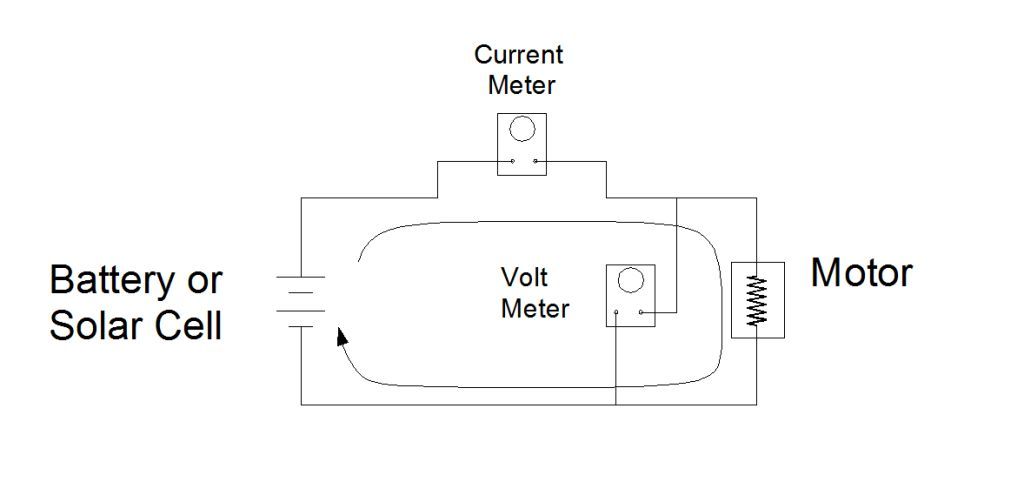
For your home the battery would be your local power company. What you are measuring is the voltage and current going to a motor. But the idea is the same.
Before you ask why you should measure power, let me point out an old saying, You can’t manage what you can’t measure.. If you want to make you home more energy efficient, you need to know how much energy you are using before you can improve it.
Or in my case, I will be using this measurement device to measure the power I am generating from my solar panels. For those of you who don’t know it, I have solar panels on my house. You can find out more about that at Sun power from my roof.
Lets build a Power Monitor
Now that we have all the information about how to do it ourselves, lets look at some ideas from the web. Here is a picture of a power monitoring circuit using a Arduino.
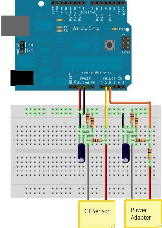
Even though this circuit uses an Arduino, the same type of circuit would work with a Raspberry Pi. The web site for this image has more information on how to build it at How to build an Arduino energy monitor.
Using an Open Energy Monitor
Before you go off and build a monitor yourself, let me tell you a secret. All the work has been done for you by a group in Golly Old England known as OpenEnergyMonitor. To give you some ideas here is a drawing of how to use their energy monitoring circuit with a Solar PV array.
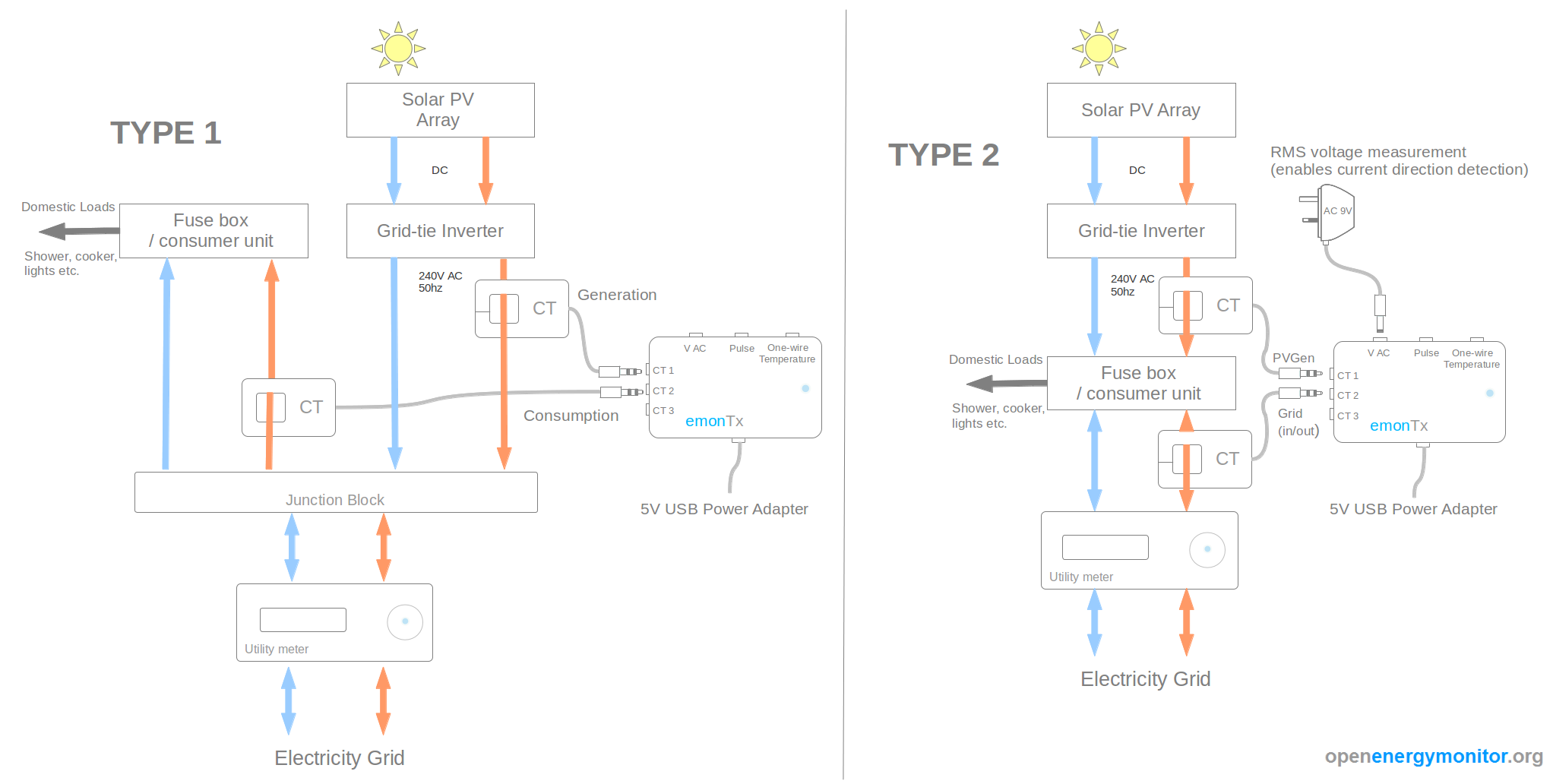
Now lest you think I forgot the Raspberry Pi, here is the information page for using the Raspberry Pi with the EmonTX.
Now you are ready to run the monitor and up load the data to their web site emoncms.org for you to view it online.
I did not discuss software. Why? Because I don’t know if you are ready for it. On the web page above is a listing of software available for Raspberry Pi. If you want to discuss the software, I will arrange to have a discussion about it at another time.
Written by John F. Moore
Last Revised: Tue 01 Sep 2020 08:10:07 PM EDT

This work is licensed under a Creative Commons Attribution-NonCommercial-ShareAlike 3.0 Unported License.