Abstract
We are going to discuss what hardware is inside your computer. We will be explaining what it is and how it words at a layman’s level.
What make a computer work?
OK, time to pop off the cover of your desk top computer and have a look around. Most people never see the inside of the computer, but today we are going to explore it.
You don’t really NEED to understand the parts of the computer to use it. Just as you do not need to be an auto mechanic to drive a car. But understanding what the parts of the computer are and how they work, might make some of the software more understandable. Besides it is sometimes useful to understand what is happening inside your computer when something goes wrong.
I should start with an apology to those of you who are viewing this on the web, and not in the class. For this talk I brought in a suite case full of hardware to examine in the class room. But it is a little hard to include that on the web page. ;-) I have included pictures and some diagrams, but it is not the same as having the object in your hand to view. So maybe it is time to consider pulling the cover off your own desktop computer. If you have a laptop, I am afraid you are out of luck for looking inside the box. With a laptop, you have the same components, and they work the same way. The difference is that they are all build on the motherboard since space and size are the reason you have a laptop.
Lets start by having a look at the names/terms used in the computer. This list is by no means complete, but it will cover the most common ones. All definitions taken from: Wikipedia, which I highly recommend, as it has some of the best human readable explanations.
802.11: or Wi-Fi denotes a set of Wireless LAN standards developed by working group 11 of the IEEE LAN/MAN Standards Committee (IEEE 802). The term is also used to refer to the original 802.11, which is now sometimes called “802.11legacy.”
The 802.11 family currently includes six over-the-air modulation techniques that all use the same protocol, the most popular (and prolific) techniques are those defined by the a, b, and g amendments to the original standard; security was originally included, and was later enhanced via the 802.11i amendment. Other standards in the family (c\u2013f, h\u2013j, n) are service enhancement and extensions, or corrections to previous specifications. 802.11b was the first widely accepted wireless networking standard, followed (somewhat counterintuitively) by 802.11a and 802.11g.
802.11b and 802.11g standards use the unlicensed 2.4 gigahertz (GHz) band. The 802.11a standard uses the 5 GHz band. Operating in an unregulated frequency band, 802.11b and 802.11g equipment can incur interference from microwave ovens, cordless phones, and other appliances using the same 2.4 GHz band.
ADC In electronics, an analog-to-digital converter (abbreviated ADC, A/D, or A to D) is a device that converts continuous signals to discrete digital numbers.
Typically, an ADC converts a voltage to a digital number. A digital-to-analog converter (DAC) performs the reverse operation.
ALU: The arithmetic logic unit/arithmetic-logic unit (ALU) of a computer’s CPU is a part of the execution unit, a core component of all CPUs. ALUs are capable of calculating the results of a wide variety of basic arithmetical computations.
Virtually all modern computer ALUs use the two’s complement binary number representation
Assembly Language or simply assembly is a human-readable notation for the machine language that a specific computer architecture uses. Machine language, a pattern of bits encoding machine operations, is made readable by replacing the raw values with symbols called mnemonics.
For example, a computer with the appropriate processor will understand this x86/IA-32 machine instruction:
10110000 01100001For programmers, however, it is easier to remember the equivalent assembly language representation:
mov al, 0x61which means to move the hexadecimal value 61 (97 decimal) into the processor register with the name “al”. The mnemonic “mov” is short for “move”, and a comma-separated list of arguments or parameters follows it; this is a typical assembly language statement.
Baud: In telecommunications and electronics, baud is a measure of the “signaling rate” which is the number of changes to the transmission media per second in a modulated signal. It is named after Emile Baudot, the inventor of the Baudot code for telegraphy.
For Example: 250 baud means that 250 signals are transmitted in one second. If each signal carries 4 bits of information then in each second 1000 bits are transmitted. This is abbreviated as 1000 bit/s.
Note : Baud rate should not be confused with data rate (also called “bits per second”). Each signalling event transmitted can carry one or more bits (as many as 256 in 256-QAM modulation) of information. When each signalling event transmitted carries one bit the baud rate and the data rate are equal. However, it is more common to make better use of bandwidth by encoding multiple bits in one event. This reduces the transmission time required for sending information.
Thus, a 2400 bit/s modem actually transmits at 600 baud, where each quadrature amplitude modulation event carries four bits of information.
BIOS in computing, stands for basic input/output system. BIOS refers to the software code run by a computer when first powered on. The primary function of BIOS is to prepare the machine so other software programs stored on various media (such as hard drives, floppies, and CDs) can load, execute, and assume control of the computer.
Bit: A bit (sometimes abbreviated b, see below) is the most basic information unit used in computing and information theory. A single bit is a one or a zero, a true or a false, a “flag” which is “on” or “off”, or in general, the quantity of information required to distinguish two mutually exclusive states from each other. A bit is like a light switch; it can be either on or off.
Byte: A byte is commonly used as a unit of storage measurement in computers, regardless of the type of data being stored.
A contiguous sequence of a fixed number of bits. On modern computers, an eight-bit byte or octet is by far the most common. This was not always the case. Certain older models have used six-, seven-, or nine-bit bytes - for instance on the 36-bit architecture of the PDP-10. Another example of a non eight-bit sequence is the 12-bit slab of the NCR-315. A byte is always atomic on the system, meaning that it is the smallest addressable unit. An eight-bit byte can hold 256 possible values (28 = 256) – enough to store an unsigned integer ranging from 0 to 255, a signed integer from -128 to 127, or a character of a seven-bit (such as ASCII) or eight-bit character encoding.
CD-Rom The CD-ROM (an abbreviation for “Compact Disc Read-Only Memory”) is a non-volatile optical data storage medium using the same physical format as audio CDs, readable by a computer with a CD-ROM drive. A CD-ROM is a flat, metallized plastic disc with digital information encoded on it in a spiral from the center to the outside edge. The CD-ROM Yellow Book standard was established in 1985 by Sony and Philips. Microsoft and Apple Computer were early enthusiasts and promoters of CD-ROMs.
Clock Signal: In electronics and synchronous digital circuits, such as most computers, a clock signal is a signal used to coordinate the actions of two or more circuits. A clock signal oscillates between a high and a low state, normally with a 50% duty cycle, and is usually a square wave. The circuits using the clock signal for synchronization may become active at either the rising or falling edge, or both (see for example DDR SDRAM), of the clock signal.
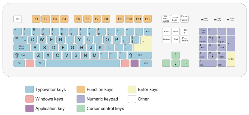
Computer Keyboard: A computer keyboard is a peripheral modelled after the typewriter keyboard. Keyboards are designed for the input of text and characters, and also to control the operation of the computer. Physically, computer keyboards are an arrangement of rectangular or near-rectangular buttons, or “keys”. Keyboards typically have characters engraved or printed on the keys; in most cases, each press of a key corresponds to a single written symbol. However, to produce some symbols requires pressing and holding several keys simultaneously, or in sequence; other keys do not produce any symbol, but instead affect the operation of the computer, or the keyboard itself.
Computer Monitor: A computer display, monitor or screen is a computer peripheral device capable of showing still or moving images generated by a computer and processed by a graphics card. Monitors generally conform to one or more display standards. Sometimes the name “display” is preferred to the word “monitor”, as the latter can be ambiguous alongside the other senses of “monitor” meaning “machine-level debugger” or “thread synchronization mechanism”. Computer displays are sometimes called heads, especially when talking about how many are connected to a computer. Once an essential component of a computer terminal, computer displays have long since become standardized peripherals in their own right.
Computer Mouse: A mouse is a handheld pointing device for computers, involving a small object fitted with one or more buttons and shaped to sit naturally under the hand. The underside of the mouse houses a device that detects the mouse’s motion relative to the flat surface on which it sits. The mouse’s 2D motion is typically translated into the motion of a pointer on the display.
Computer Trackball: A trackball is a pointing device consisting of a ball housed in a socket containing sensors to detect rotation of the ball about two axes – like an upside-down mouse, but with the ball sticking out more. The user rolls the ball with their thumb, fingers, or the palm of their hand to move a cursor. Tracker balls are common on CAD workstations for ease of use and, before the advent of the trackpad, on portable computers, where there may be no desk space on which to use a mouse. Some clip onto the side of the keyboard and have integral buttons which have the same function as mouse buttons. Trackballs are sometimes seen on computerised special-purpose workstations, such as the radar consoles in an air-traffic control room or sonar equipment on a ship or submarine. Modern installations of such equipment may use mice instead, since most people now already know how to use one. However, military mobile anti-aircraft radars and submarine sonars tend to continue using trackballs, since they can be made much more durable and are better fit for fast emergency use.
CPU: A central processing unit (CPU) refers to part of a computer that interprets and executes instructions and data contained in software. The more generic term processor is sometimes used to refer to a CPU as well; see processor (disambiguation) for other uses of this term. Microprocessors are CPUs that are manufactured on integrated circuits, often as a single-chip package. Since the mid-1970s, these single-chip microprocessors have become the most common and prominent implementations of CPUs, and today the term is almost always applied to this form.
CPU Cache A CPU cache is a cache used by the central processing unit of a computer to reduce the average time to access memory. The cache is a smaller, faster memory which stores copies of the data from the most frequently used main memory locations. As long as most memory accesses are to cached memory locations, the average latency of memory accesses will be closer to the cache latency than to the latency of main memory.
CRT The cathode ray tube or CRT, invented by Karl Ferdinand Braun, is the display device used in most computer displays, video monitors, televisions and oscilloscopes. The CRT developed from Philo Farnsworth’s work was used in all television sets until the late 20th century and the advent of plasma screens, LCDs, DLP, OLED displays, and other technologies.
DAC In electronics, a digital-to-analog converter (DAC or D-to-A) is a device for converting a digital (usually binary) code to an analog signal (current, voltage or charges). Digital-to-Analog Converters are the interface between the abstract digital world and the analog real life. Simple switches, a network of resistors, current sources or capacitors may implement this conversion.
An analog-to-digital converter (ADC) performs the reverse operation.
Dot Matrix A dot matrix printer or impact matrix printer refers to a type of computer printer with a print head that runs back and forth on the page and prints by impact, striking an ink-soaked cloth ribbon against the paper, much like a typewriter. Unlike a typewriter or daisy wheel printer, letters are drawn out of a dot matrix, and thus, varied fonts and arbitrary graphics can be produced. Because the printing involves mechanical pressure, these printers can create carbon copies and carbonless copies.
DVD (sometimes called a Digital Versatile Disc) is an optical disc storage media format that can be used for data storage, including movies with high video and sound quality. DVDs resemble compact discs as their physical dimensions are the same (12cm in diameter) but they are encoded in a different format and at a much higher density. DVDs use the UDF file system which is an extension of the ISO 9660 Standard used for CD-ROMs.
Ethernet is a frame-based computer networking technology for local area networks (LANs). The name comes from the physical concept of ether. It defines wiring and signaling for the physical layer, and frame formats and protocols for the media access control (MAC)/data link layer of the OSI model. Ethernet is mostly standardized as IEEEs 802.3. It has become the most widespread LAN technology in use during the 1990s to the present, and has largely replaced all other LAN standards such as token ring, FDDI, and ARCNET.
Flash Memory is a form of EEPROM(Electrically-Erasable Programmable Read-Only Memory) that allows multiple memory locations to be erased or written in one programming operation. In layman’s terms, it is a form of rewritable memory chip that, unlike a Random Access Memory chip, holds its content without the need of a power supply. It is also an example of a Non-Volatile Read Write Memory (NVRWM). The memory is commonly used in memory cards, USB flash drives, MP3 players, digital cameras and mobile phones.
Floppy Disk: A floppy disk is a data storage device that is composed of a circular piece of thin, flexible (i.e. “floppy”) magnetic storage medium encased in a square or rectangular plastic wallet. Floppy disks are read and written by a floppy disk drive or FDD, the latter initialism not to be confused with “fixed disk drive”, which is an old IBM term for a hard disk drive.
Hard Disk: A hard disk uses rigid rotating platters (disks). Each platter has a planar magnetic surface on which digital data may be stored. Information is written to the disk by transmitting an electromagnetic flux through an antenna or read-write head that is very close to a magnetic material, which in turn changes its polarization due to the flux. The information can be read back by a read-write head because the magnetic fields cause electrical change in the read-write head as it passes over a platter.
Hertz: One hertz simply means “one per second” (1 / s); 100 Hz means “one hundred per second”, and so on. The unit may be applied to any periodic event \u2013 for example, a clock might be said to tick at 1 Hz, or a human heart might be said to beat at 1.2 Hz. Frequency of random events, such as radioactive decays, is expressed in becquerels.
Inkjet Most current inkjets (Epson being a notable exception) work by having a print cartridge with a series of tiny electrically-heated chambers constructed by photolithography. To produce an image, the printer runs a pulse of current through the heating elements. A steam explosion in the chamber forms a bubble, which propels a droplet of ink onto the paper (hence Canon’s tradename for its inkjets, Bubblejet). When the bubble condenses, surplus ink is sucked back up from the printing surface. The ink’s surface tension pumps another charge of ink into the chamber through a narrow channel attached to an ink reservoir. Epson’s Micro Piezo technology uses a piezoelectric crystal in each nozzle instead of a heating element. When current is applied, the crystal bends, forcing a droplet of ink from the nozzle.
ISA: Industry Standard Architecuter, originated as an 8-bit system in the IBM PC in 1981, and was extended in 1983 as the XT bus architecture. The modern 16-bit standard was introduced in 1984. Designed to connect peripheral cards to the motherboard, the protocol also allows for bus mastering although only the first 16 MB of main memory is available for direct access. The 8-bit bus ran at 4.77 MHz, while the 16-bit bus operated at 8 MHz. In reference to the XT bus, it is sometimes referred to as the AT bus architecture. It was also available on some non-IBM compatible machines such as the short-lived AT&T Hobbit and later PowerPC based BeBox.
Jumpers: In electronics and particularly computing, a jumper is two or more connecting points that can be conveniently shorted together to set up or adjust a printed circuit board, such as a computer’s motherboard.
Jumpers are arranged in groups called jumper blocks, each group having at least one pair of contact points and often more. In general, each contact in a jumper block terminates in a small metal pin. An appropriately sized conductive sleeve called a shunt is slipped over the pins to complete the circuit. (In everyday usage, shunts are very commonly but incorrectly called “jumpers”.)
Laser Printer A laser printer is a common type of computer printer that produces high quality printing, and is able to produce both text and graphics.
The process is very similar to the type of dry process photocopier first produced by Xerox. Indeed, the first laser printer was created by Xerox researcher Gary Starkweather by modifying a Xerox copier in- Laser printing eventually became a multibillion-dollar business for Xerox.
LCD A liquid crystal display (LCD) is a thin, flat display device made up of any number of color or monochrome pixels arrayed in front of a light source or reflector. It is prized by engineers because it uses very small amounts of electric power, and is therefore suitable for use in battery-powered electronic devices.
Light Pen: A lightpen is a device similar to a touch screen, but is facilitated by use of a special light sensitive pen instead of the finger. The advantage of using a pen is that more accurate screen input is possible than with a touch screen. Also, a light pen can work with any CRT-based monitor, not just with a special touch screen. However, light pens cannot work with LCD screens, projectors etc…
Logic Gate A logic gate is an arrangement of controlled switches used to calculate operations using Boolean algebra in digital circuits.
Machine Language A system of codes directly understandable by a computer’s CPU is termed this CPU’s native or machine language. Although machine code may seem similar to assembly language they are in fact two different types of languages. Assembly code consists of both binary numbers and simple words whereas machine code is composed only of the two binary digits 0 and 1. Every CPU model has its own machine language, although there is considerable overlap between some. If CPU A understands the full language of CPU B it is said that A is compatible with B. CPU B may not be compatible with CPU A, as A may know a few codes that B does not.
Memory Management is the act of managing computer memory. In its simpler forms this involves providing ways to allocate portions of memory to programs at their request and free it back to the system for reuse when no longer needed.
Virtual memory systems increase the effectively available amount of RAM using disk swapping and the quality of the virtual memory manager can have a big impact on overall system performance.
Motherboard: A motherboard, also known as a main board, mainboard, logic board or system board, and sometimes abbreviated as mobo, is the central or primary circuit board making up a complex electronic system, such as a computer.
NIC A network card (also called network adapter, network interface card, NIC, etc.) is a piece of computer hardware designed to provide for computer communication over a computer network.
Whereas network cards used to be expansion cards to plug into a computer bus, most newer computers have a network interface built into the motherboard, so a separate network card is not required unless multiple interfaces are needed or some other type of network is used.
The card implements the electronic circuitry required to communicate using a specific physical layer and data link layer standard such as ethernet or token ring. This provides a base for a full network protocol stack, allowing communication among small groups of computers on the same LAN and large-scale network communications through routable protocols, such as IP.
A network card typically has a twisted pair, BNC, or AUI socket where the network cable is connected, and a few LEDs to inform the user of whether the network is active, and whether or not there is data being transmitted on it. The Network Cards are typically available in 10/100/1000 Mbit/s. This means they can support a transfer rate of 10 or 100 or 1000 Mbit/s.
Opcode In computer science, an Opcode is the portion of a machine language instruction that specifies the operation to be performed. The term is an abbreviation of Operation Code. Their specification and format will be laid out in the instruction set architecture (ISA) of the computer hardware component in question\u2014normally a CPU, but possibly a more specialised unit. A complete machine language instruction contains an opcode and, optionally, the specification of one or more operands\u2014what data the operation should act upon. Some operations have implicit operands, or indeed none. Some ISAs have instructions with defined fields for opcodes and operands, while others (e.g. the Intel x86 architecture) have a more complicated and ad-hoc structure.
The operands upon which opcodes operate may, depending on CPU architecture, consist of registers, values in memory, values stored on the stack, I/O ports, the bus, etc. The operations an opcode may specify can include arithmetic, data copying, logical operations, and program control.
Parallel Port: In computing, a parallel port is an interface from a computer system where data is transferred in or out in parallel, that is, on more than one wire. A parallel port carries one bit on each wire thus multiplying the transfer rate obtainable over a single cable (contrast serial port). There are also several extra wires on the port that are used for control and status signals to indicate when data is ready to be sent or received, initiate a reset, indicate an error condition (such as paper out), and so forth.
PC A personal computer or PC is generally a microcomputer intended to be used by one person at a time, and suitable for general purpose tasks such as word processing, programming, multimedia editing or game play, usually used to run software not written by the user. Unlike minicomputers, a personal computer is often owned by the person using it, indicating a low cost of purchase and simplicity of operation. The user of a modern personal computer may have significant knowledge of the operating environment and application programs, but is not necessarily interested in programming nor even able to write programs for the computer.
PCI: The PCI bus is common in modern PCs, where it has displaced ISA and VESA Local Bus as the standard expansion bus, but it also appears in many other computer types. The bus will eventually be succeeded by PCI Express and other technologies, which have already started to appear in new computers.
The PCI specification covers the physical size of the bus (including wire spacing), electrical characteristics, bus timing, and protocols.
PC Card / PCMCIA: The PCMCIA is the Personal Computer Memory Card International Association, an industry trade association that creates standards for notebook computer peripheral devices.
The best known such devices are known as PC Cards (formerly PCMCIA cards). A later revision of the PC Card is known as CardBus. The PCMCIA is also developing a new notebook peripheral specification called Newcard or ExpressCard. The initialism “PCMCIA” was jokingly expanded as “People Can’t Memorize Computer Industry Acronyms”.
The first PC cards (PCMCIA) were Type I, and supported actual Memory Cards (e.g. ATA Type I Flash Memory Cards), such as DRAM or Flash memories. Type II cards added I/O support in addition to memory applications, and type III expanded on this. The ports role as I/O for various devices has largely superseded its role as a Memory Card, but this role did spawn a generation of flash memory cards that set out to improve on the size and features of ATA Type I cards (CompactFlash, MiniCard, and SSFDC(Smartmedia)).
Processor Register In computer architecture, a processor register is a small amount of very fast computer memory used to speed the execution of computer programs by providing quick access to commonly used values – typically, the values being in the midst of a calculation at a given point in time. Most, but not all, modern computer architectures operate on the principle of moving data from main memory into registers, operating on them, then moving the result back into main memory – a so-called load-store architecture.
Processor registers are the top of the memory hierarchy, and provide the fastest way for the system to access data. Registers are normally measured by the number of bits they can hold, for example, an “8-bit register” or a “32-bit register”. Registers are now usually implemented as a register file, but they have also been implemented using individual flip-flops, high speed core memory, thin film memory, and other ways in various machines
PS/2: the mini-DIN mouse and keyboard connection ports which were introduced by the IBM Personal System/2. Because of the old AT type of keyboard connection, the plugs were usually too cluttered and difficult to handle. So when the new technology came along, and it had some success. It could handle the old type of keyboards with an adapter to fit between them. It’s technically the same connection, but it’s more stable, better speed and the plug has been replaced. Most modern computers have two of those ports.
RAM: is an acronym for random access memory. is a type of computer storage (in practice only computer chips) whose contents can be accessed in any (i.e., random) order. This is in contrast to sequential memory devices such as magnetic tapes, discs and drums, in which the mechanical movement of the storage medium forces the computer to access data in a fixed order.
ROM: Read-only memory (ROM) is used as a storage medium in computers. Because it cannot (easily) be written to, its main uses lie in the distribution of firmware (software that is very closely related to hardware, and not likely to need frequent upgrading).
RS-232: In telecommunications, RS-232 is a standard for serial binary data interconnection between a DTE (Data terminal equipment) and a DCE (Data communication equipment). It is commonly used in computer serial ports.
Serial Port: In computing, a serial port is an interface on a computer system with which information is transferred in or out one bit at a time (contrast parallel port). Throughout most of the history of personal computers, this was accomplished using the RS-232 standard over simple cables connecting the computer to a device such as a terminal or modem. Mice, keyboards, and other devices were also often connected this way.
SVGA: Originally, it was an extension to the VGA standard first released by IBM in 1987. Unlike VGA – a purely IBM-defined standard – Super VGA was defined by the Video Electronics Standards Association (VESA), an open consortium set up to promote interoperability and define standards.
Graphics Tablet: A graphics tablet is a computer peripheral device that allows one to hand-draw images directly into a computer, generally through an imaging program. Graphics tablets consist of a flat surface upon which the user may “draw” an image using an attached stylus, a pen-like drawing apparatus. The image generally does not appear on the tablet itself but, rather, is displayed on the computer monitor.
Tape Drive A tape drive, also known as a streamer, is a peripheral device that reads and writes data stored on a magnetic tape or a punched tape. It is typically used for archival storage of data stored on hard drives. Tape drives are sequential-access, and must wind past all preceding data to read any one particular piece of data. They are not the fastest form of data storage, as they are sequential, but are long lasting and cost efficient. Modern LTO drives can reach burst transfer rates of over 160 MB/s, with average transfer rates in the 80 MB/s range. Tape drives can be connected with SCSI (most common), parallel port, IDE, USB, FireWire or Optical Fibre.
Touch Screen: Touchscreens, touch screens, touch panels or touchscreen panels are display overlays which are typically either pressure-sensitive (resistive), electrically-sensitive (capacitance), acoustically-sensitive (SAW - surface acoustic wave) or photo-sensitive (infra-red). The effect of such overlays allows a display to be used as an input device, removing the keyboard and/or the mouse as the primary input device for interacting with the display’s content. Such displays can be attached to computers or, as terminals, to networks.
TTL Transistor-Transistor Logic (TTL) is a class of digital circuits built from bipolar junction transistors (BJT), and resistors. It is notable for being a widespread integrated circuit (IC) family used in many applications such as computers, industrial controls, music synthesizers, and electronic test and measurement instruments.
USB: Universal Serial Bus (USB) provides a serial bus standard for connecting devices, usually to a computer, but it also is in use on other devices such as set-top boxes, game consoles such as Sony’s PlayStation 2, Microsoft’s Xbox 360, Nintendo Revolution and PDAs
Virtual Memeory or virtual memory addressing is a feature of computer systems wherein “permanent” data storage is used to assist in handling processing functions, thereby freeing more RAM or main memory (i.e. “active” or “fast” memory) to be used by running software. The use of virtual memory, though slower than if more RAM were added, allows a computer system to handle larger files and operate with more memory “headroom” than the computer actually physically possesses.
VGA: Video Graphics Array (VGA) is a computer display standard first marketed in 1987 by IBM. VGA belongs to a family of earlier IBM video standards and largely remains backward compatible with them. VGA can be seen as an enhancement of and successor to the previous EGA and CGA graphics adapters. MCGA, also produced by IBM, is a simpler version of the VGA hardware.
Word In computing, “word” is a term for the natural unit of data used by a particular computer design. A word is simply a fixed-sized group of bits that are handled together by the machine. The word size (or length) is an important characteristic of a computer architecture.
The size of a word influences many aspects of a computer’s structure and operation. The majority of the registers in the computer are usually word-sized. The typical numeric value manipulated by the computer is probably word sized. The amount of data transferred between the processing part of the computer and the memory system is most often a word. An address used to designate a location in memory often fits in a word.
Modern computers usually have a word size of 16, 32, or 64 bits.
WiFi: (sometimes written Wi-fi, WiFi, Wifi, wifi) is a trademark for sets of product compatibility standards for wireless local area networks (WLANs). Wi-Fi, short for “Wireless Fidelity”, was intended to allow mobile devices, such as laptop computers and personal digital assistants (PDAs) to connect to local area networks, but is now often used for Internet access and wireless VoIP phones. Desktop computers can use Wi-Fi too, allowing offices and homes to be networked without expensive wiring. Many computers are sold today with Wi-Fi built-in; others require adding a Wi-Fi network card. Other devices, such as digital cameras, are sometimes equipped with Wi-Fi.
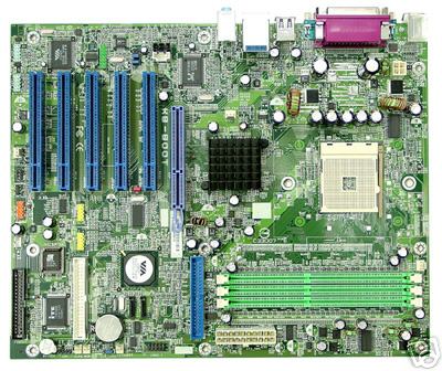
The Motherboard
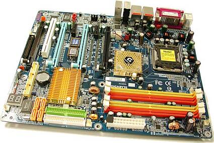
I think the best way to talk about motherboards is to look at a few of them and talk about them. So here are a few pictures of mother boards I collected for discussion.
This first one is a good diagonal view of a motherboard so we can see the connectors clearly.
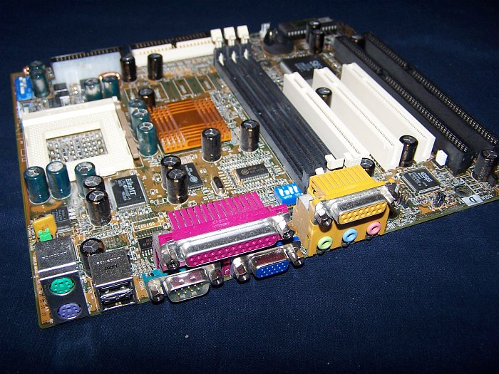
This next one is also an angle view, but from the other side.
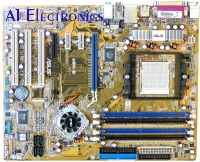
This view is a motherboard from the top, showing the fan over the processor.

This is another top view of a motherboard so you see the connectors clearly.
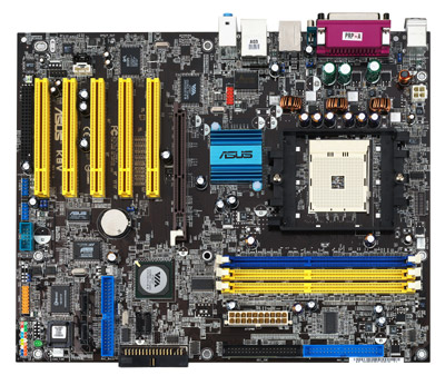
Lastly we have one more from the top. It is a larger mother board so it might be a bit clearer.
Now lets see if I can get a board diagram to work.
OK now that we have seen what the motherboard looks like, lets review a few of the components found there. When I use a term defined above I will link to the definition instead of explaining it again.
The Motherboard is the heart of the computer since it contains the CPU. In the PC the CPU consists of a single chip, while in some larger computers, especially mainframes, the CPU might be a complete circuit board. No discussion of computer hardware would be complete without a discussion of a CPU. But I know this is not a hardware engineering course, so we will go through it only superficially.
CPU
The CPU consists of a number of sub parts. These include the ALU, the Process Registers, the CPU Cache, and the Memory Management Unit. This is not a complete list of all the sub parts of the CPU, there are whole books on that subject, along with jobs at Intel.
Here is a reasonable drawing of what a CPU does and how it works.
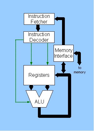
Another name for Instructions is opcode. The opcode is the basic unit of control in the CPU. When a CPU is designed, the opcodes are defined and usually hard coded into the CPU. These opcodes define what the CPU does.
Some of you are probably familiar with assembly code, also known as assembly language. Assembly code is the human readable version of machine language. For those of you who are not familiar with machine code, let me see if I can make it understandable.
A computer is a series of registers and logic gates. In the computer everything is stored as ON and OFF, commonly referred to as 1 and 0. This is easy to visualize if you think of a light switch, the light is either ON or it is OFF. The computer use a number system based on 2, also known as a base 2 system, (0, 1). Our normal number system is a base 10, (0, 1, 2, 3, 4, 5, 6, 7, 8, 9).
This might seem cumbersome to us mortals, but to a computer a number system of only 2 numbers works fine. The trick to understanding how things work is to visualize how a computer can work with these 2 values, 0 and 1.
Lets start by seeing how to convert from base 10 to base 2. Since base 2 is 2 raised to different powers, we could view it as a table:
| Binary data | Base 2 | Hex (Base 16) | Base 10 |
|---|---|---|---|
| 0000 0000 | 0 | 0x00 | 0 |
| 0000 0001 | 20 | 0x01 | 1 |
| 0000 0010 | 21 | 0x02 | 2 |
| 0000 0100 | 22 | 0x04 | 4 |
| 0000 1000 | 23 | 0x08 | 8 |
| 0001 0000 | 24 | 0x10 | 16 |
| 0010 0000 | 25 | 0x20 | 32 |
| 0100 0000 | 26 | 0x40 | 64 |
| 1000 0000 | 27 | 0x80 | 128 |
| 1100 0000 | 27 + 26 | 0xC0 | 192 |
| 1110 0000 | 27 + 26 + 25 | 0xE0 | 224 |
| 1111 0000 | 27 + 26 + 25 + 24 | 0xF0 | 240 |
| 1111 1000 | 27 + 26 + 25 + 24 + 23 | 0xF8 | 248 |
| 1111 1100 | 27 + 26 + 25 + 24 + 23 + 22 | 0xFC | 252 |
| 1111 1110 | 27 + 26 + 25 + 24 + 23 + 22 + 21 | 0xFE | 254 |
| 1111 1111 | 27 + 26 + 25 + 24 + 23 + 22 + 21 + 20 | 0xFF | 255 |
OK now that we understand how we get from our usual numbers, base 10, to computer numbers, base 2, we can have a look at some basic computer operations. Rather than me trying to create this myself, I copied this page from Wikipedia: Binary Arithmetic.
So now that we understand how binary arithmetic is done you might have guessed, that this operation is performed by the ALU (Arithmetic Logic Unit).
Besides the ALU we have Registers which work as temporary storage locations for the ALU. Another part of the CPU you hear about often is the CPU cache. The cache is a method for keeping the ALU busy by prefetching instructions and data before it is needed by the ALU.
Lastly in our current discussion, we will address memory management. Most computers have less physical memory than they can address. With modern computers having 32 Address lines, they can talk to 4,294,967,296 words of memory. When you factor in that computers today have 32 data lines, it means that they can access more than 16 Gigabytes of memory. So what happens is that each program thinks it has 16 gigabytes of memory for it’s use. But realize that today’s PCs are multitasking, so they use a technique called Virtual Memory to swap the active portions of computer code between physical memory and the hard disk. So what happens when a program tries to access a portion of memory which has another applications code in? The answer is that it is blocked while the OS swaps out the current resident of that part of memory, and swaps in the correct code for the application. Think of it as a game where each application thinks it owns all the memory of the CPU.
Bits, Bytes, and Words
Before we continue, we should take a side trip to understand bits, bytes, and words of memory. A Bit is a single data point. A bit can be either ON or OFF. In the early days of ICs (Integrated Circuits) they used a logic known as TTL (Transistor Transistor Logic). In the TTL world an ON signal was supposed to be 3.5 to 5 volts. While an OFF signal was 0.75 to 0 volts. (Or that is what we used when I tested hardware.) The logic chips used a power supply voltage of 5 volts. So ON was the transistor turned on, and OFF was the transistor turned off.
The Byte was a collection of 8 bits. Why 8? Well the early computers were 8 bit computers with 8 data lines. Also 8 divides evenly in a Base 2 system. The original IBM PC was an 8 bit system using the Intel 8088 CPU. It had 16 address lines and 8 data lines. As had the 8080 before it.
A Word of memory refers to the smallest addressable piece of memory. So this would mean that on a Pentium CPU, the word size is 32 bits. Meaning that each address expects to find 32 bits of data available. This value of the Word affects the size of registers in the CPU as well as the data architecture of the whole computer.
The upshot of this is that even though we refer to sizes in bytes, typically, that is not the same as the way the computer sees it.
RAM
RAM (Random Access Memory) is the interface between the larger but slower storage devices and the CPU. RAM is sometimes referred to as scratch pad memory since it’s contents disappear when the power is turned off. RAM is best viewed as a very large set of mail boxes. Each of the RAM chips has two set of information pins, data and address.
The Data pins of the RAM chip are used to read and write the contents. These pins provide access to the values stored in the chip at a given address.
The address pins of the RAM chip works as a location pointer to the internal contents. Today, most computers use banks of ram chips. The reason is that most CPUs today use 32 bits for their computer words. But we still talk about bytes of memory. The upshot is that each address in a 32 bit CPU must see 4 bytes of memory, ie 32 bits. So a memory architecture, which uses byte wide RAM, would need 4 chips at each address.
One interesting fact these days is that the CPU typically operates much faster than the RAM does. For example my server at home runs at 1900 Mega hertz, but the memory only runs at 266 Mega hertz. This help explain some of the issues with processing speed as opposed to CPU speed.
ROM
Long term storage on the motherboard is accomplished using ROM (Read Only Memory). These are typically the chips used to store the BIOS (Basic Input/Output System) for the CPU. In many embedded system the only program storage is ROM.
There is usually two or more types of ROM on today’s motherboards. The first type is Write Once/Read Many type. This were also known as fusible or masked Roms in the past. The way these work is the program is burned into the chip using a programming tool. This makes these chips very cheap to manufacture, but to change the program you have to throw away the chip.
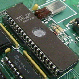
One early change in the ROM, also know as a PROM for Programmable Read Only Memory, was the ability to erase the memory and reuse the chip. The early ones were UV (Ultra Violet) erasable EPROMs. I mention this one because I like to pass one of these around. They have a clear window on the top of the chip case, so you can actually see the chip and the fine wires used to attach the chip to the case.
Here is a picture of a microcontroler chip which has a build in EPROM so you can see what I am talking about.
The second type of ROM on today’s motherboards is the EEPROM, (Electrically Erasable Programmable Read Only Memory), also known as the Flash Memory. This allows you to erase and reprogram the memory. I would imagine some of you have a flash bios in your computer.
BIOS
While we are discussing ROM, we should discuss the BIOS. When the CPU is first turned on, or reset, it needs some way to find it’s first instruction. So the CPU manufactures decided that the first instruction would be hard coded. So the CPU goes to a specific location, loads the data, and executes this data.
The first data is normally a jump into the initial BIOS code. This is also what happens when you press the reset button, if you have one.
The BIOS itself instructs the computer on what hardware is available on the system and usually runs the POST (Power On Self Test) to see that the motherboard is OK. Once the POST is done, the user can go into the bios setup to specify the hardware, or the system loads the basic drivers for the installed hardware.
Clock
The Motherboard contains 2 clocks. The first clock is the Clock Signal. The clock signal is best thought of as the drum beat for the computer. The rising and falling edges of the signal trigger different operations on the motherboard.
You see the logic chips on the motherboard need a clock to make sure that all the data transitions happen in the correct order. This ordering is handled by the chips themselves using the clock ticks to synchronize them.
The second type of clock is know as the RTC (Real Time Clock). This is the clock powered by a battery when the system is turned off. It keeps track of the time by counting the number of ticks since 1970-01-01 00:00:00 UTC. For a 32 bit register, this should be enough to reach: 2038-01-19 03:14:07 UTC. The clock from the original IBM PC produced a time interrupt at the rate of 18.206 ticks per second. This is not always an accurate time interval, so it is often good to correct the RTC in the system.
Expansion Slots
The Motherboard has connectors on it to allow you to add additional controllers to the motherboard. These were anticipated to be things like display boards, disk controllers, I/O cards, and others. To facilitate this the Motherboard is configured with connectors. The first ones of these were known as ISA bus. These connectors allowed the motherboard to be expanded by adding circuit boards to the motherboard.
After the ISA bus there came a series of connector specifications. MCA (Micro Channel Architecture), EISA (Extended Industrial Standard Architecture), VESA Local Bus, PCI (Peripheral Component Interconnect), and AGP (Accelerated Graphics Port). One connector which is present on a Laptop and a few desktops is the PC Card which I still call PCMCIA cards.
The bus provided power and an interface to the data and address lines of the CPU. Through this mechanism the system was able to expand after the initial sale. This also allowed new functions to be added to the computer after it was designed. The bus for these cards typically runs more slowly than the CPU clock cycle.
There are a number of other connectors on the motherboard which connect peripherals such as hard disks, floppy disks, and power to the board. These connectors will come up later when we discuss computer storage systems.
Jumpers
Many motherboards contain jumpers to allow modifications to some parameters. Many motherboards will accommodate more than one speed for the CPU. So there is a jumper to select which clock speed you want for your CPU.
I will not go into the jumpers since they are specific to the board in question. Be careful not to change any of the jumpers unless you know what you are doing. Often if you change a jumper it will cause your computer to stop working.
Control Chips
There are today many more chips on the motherboard today than originally planned for. Today it is not uncommon to find a Video controller, hard disc controller, floppy disk controller, serial interface, parallel interface, USB interface, as well as mouse and keyboard interface chips. Since I intend to discuss these chips as though they were add on boards or peripherals, I will skip them for now.
Input Devices
A Personal Computer is designed for user input. But to talk to the computer we need one or more input devices. Lets do a survey of the common, and less common input devices for the PC.
Keyboard
Probably the input device most people are familiar with is the Computer Keyboard. The keyboard is really just a group of momentary switches arranged in a grid. When each key is pressed it sends a signal to the keyboard controller chip on the motherboard. This chip then generates a code which is passed to the Operating System.
In the Linux OS, the keycodes are mapped based on the contents of a keyboard control file. On this Debian laptop the keycodes are being interpreted from a file named: /etc/console/boottime.kmap.gz but on other system it would be: /usr/share/keymaps/i386/qwerty/us.kmap.gz
The reason I mention the file for the keymap is that this is where I can swap the Caps-Lock and Left-Control keys. All I need to do is go into the file and change the values as follows.
      keycode  58 = Caps_Lock
      keycode  97 = Control
Get changed to:
      keycode  58 = Control
      keycode  97 = Caps_Lock
Once that is done, you save the file, and tell the OS to use that keymap file when it boots. You now have the control key next to the A, and the caps lock in the lower left corner. Of course when someone else tries to use your computer, it drives them crazy, but that is their problem. ;-)
Mouse
The second most common input device is the Computer Mouse. The mouse is a 2 dimensional pointing device, as can be see below.
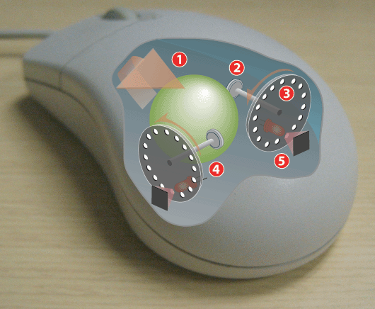
As the ball moves, it rotates the wheels, which interrupt the light from the LED to the photo transistor. This creates our familiar ON and OFF sequence. The mouse is a relative device, meaning that it only indicates movement by sending pulses, either positive or negative. An absolute device would be a light pen which gives position and movement to the OS. The mouse communicates with the PC via a 3 byte serial interface.
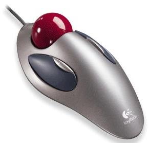
Trackball
The Computer Trackball is a close relative of the mouse. In many ways it is an inverted mouse. Instead of moving the case of the mouse to turn the ball, with the trackball you move the ball directly. Some people prefer this method since it gives them better control. One advantage I find is the ability to use a track ball on a computer stand instead of a mouse.
Light Pen
The Light Pen is another input device. The light pen is basically a photo transistor at the end of a wire. When the electron gun of a CRT points at the light pen, it triggers a response in the computer. This device has fallen out of favor since it requires the user to hold the pen in front of a monitor for long periods. Since that is a tiring position, it has been replaced with the computer mouse. It is still used in some places where it’s superior accuracy is needed.
Graphics Tablet
Another input device, often used by artists, is the Graphics Tablet. This device consists of a grid of wires which are activated by pressure from the stylus. These devices are used to create electronic free hand drawings. I have read that a number of cartoon strips are now being produced electronically using graphics tablets.
If you want to have fun, and you have access to a graphics tablet, try using Gimp with a graphics tablet. It is a trip being able to draw free hand on a computer screen.
Touch Screen
A close relative of the graphics tablet is the Touch Screen. These have taken on a much broader use with the current crop of PDAs. The touch screen has been used for inputs to many dedicated devices. The technology consists of a grid again and the stylus is the finger for dedicated terminals. Or a grid and a stylus for small screens as seen on a PDA.
One of the things that makes the touch screen so useful is the ability to redefine an area. Since the input is happening on top of a display, the definition of the touch can change depending on previous inputs. With dedicated terminals this is a real advantage since it means you can use a menu tree to arrive at a selection. Or with something like a PDA, you can use the same input surface for many different applications.
Ports
The PC contains a number of input/outputs known as ports. Basically a port is a communication device which formats data according to a protocol. We are going to look at hardware interfaces present in the PC. We will only discuss the protocols as they affect the hardware.
Serial Ports
One of the early interfaces between computers was the Serial Port. This is a method of moving data one bit at a time over a wire. The serial port chip uses a protocol known as RS-232 which defines the order and timing of the bits on the communication line.
The serial port is an Asynchronous port which transmits one bit of data at a time, usually connecting to the UART Chip. Serial Ports are commonly found on the majority of PC Compatible computers. Usually referred to as a DB9 or DB25 connection both of which adhere to the RS-232c interface standard and defined in ISO 2110 and ISO 4902. DB9 Serial connections are now commonly found on modern PC’s where DB25 is commonly found on older computers.
The serial port is not used as much any more as many of it’s functions have been taken over by the USB port. In the past this port was used for Terminals, Mice, Modems, and some Printers.
USB
The serial interface which was previously handled by the serial port, is now being taken over by the USB port. One distinct advantage of USB over serial is that multiple devices can talk to the USB port as the same time, while serial can only deal with one device at a time.
USB (Universal Serial Bus) is a new external bus developed by Intel, Compaq, DEC, IBM, Microsoft, NEC and Northern Telcom and released to the public in 1996 with the Intel 430HX Triton II Mother Board. USB has the capability of transferring 12 Mbps, supporting up to 127 devices and only utilizing one IRQ. For PC computers to take advantage of USB the user must be running Windows 95 OSR2, Windows 98 or Windows 2000. Linux users also have the capability of running USB with the proper support drivers installed. To determine if your computer supports USB on the back, front or sides of the computer look for a small connector with the following symbol.
USB cables are hot swappable which allows users to connect and disconnect the cable while the computer is on without any physical damage to the cable.
Parallel Ports
The Parallel Port has typically been used as a printer interface. This port uses a 25 pin connector and sends data 8 bits at a time. In the past this port has been used for some Tape drives.
TYPES OF PARALLEL PORTS
Unidirectional - 4-bit standard port which by factory default did not have the capability of transferring data both ways.
Bi-directional - 8-bit standard port which was released with the introduction of the PS/2 port in 1987 by IBM and are still found in computers today. The Bi-directional port is cable of sending 8-bits input and output. Today on multifunction printers this port can be referred to as a bi-directional, Centronics, PS/2 type or standard port.
EPP - The Enhanced Parallel Port (EPP) was developed in 1991 by Intel, Xircom and Zenith Data Systems and operates close to ISA bus speed and can achieve transfer rates up to 1 to 2MB/sec of data.
EPP version 1.7 released in 1992 and later adapted into the IEEE 1284 standard. All additional features are adapted into the IEEE standard.
EPP version 1.9 never existed.
ECP - The Enhanced Capabilities Port (ECP) was developed by Microsoft and Hewlett-Packard and announced in 1992 is an additional enhanced Parallel port. Unfortunately with ECP it requires an additional DMA channel which can cause resource conflicts.
Network Interface Card
A computer takes on a whole new meaning once it is connected to an Ethernet Network. Since most PC support Ethernet we will use it as the default interface for the NIC. This transformation happens because the computer is now able to access and communicate with other computers.
A NIC or Network Interface Card is a circuit board or chip, which allows the computer to communicate to other computers on a Network. This board when connected to a cable or other method of transferring data such as infrared can share resources, information and computer hardware. Local or Wide area networks are generally used for large businesses as well as are beginning to be found in homes as home users begin to have more than one computer. Utilizing network cards to connect to a network allow users to share data such as companies being able to have the capability of having a database that can be accessed all at the same time send and receive e-mail internally within the company or share hardware devices such as printers.
BNC As illustrated in the above picture the BNC connector is a round connector which is used for Thinnet or 10Base-2 Local Area Network.
DB9 (RJ45 JACK) The DB9 connector not to be confused with the Serial Port or sometimes referred to as the RJ45 JACK not to be confused with the RJ45 connection is used with Token Ring networks.
DB15 The DB15 connector is used for a Thicknet or 10Base-5 Local area network.
RJ45 Today one of the most popular types of connections used with computer networks. RJ45 looks similar to a phone connector or RJ11 connector however is slightly larger.
LED The LED’s as shown in the above illustration indicates if it detects a network generally by a green light which may flash as it communicates and then a red light which indicates collisions which will generally flash or not flash at all.
Miscellaneous Devices
There are still more devices such as joy stick, midi keyboards, scanners, or even dedicated controllers. The range of dedicated controllers gets into the things like bar code scanners, or smoke detectors, or X10 controllers. The musical inputs run the gamut from keyboards, and microphones, to drum machines, and all types of signal processing controllers. The scanners, can cover anything from video recorders to still cameras. But I am sure you get the idea.
One of the interesting features of the PC is how flexable a general purpose computer can be. Pretty much anything that can be converted to digital input can be handled by the PC.
ADC
Two interesting topics, at least to me are the Analog to Digital and Digital to Analog converters. They are a key component in bring sound to the computer. Lets take a look at the ADC first.
Basically the Analog to Digital convert performs it’s job by sampling the analog input at a defined interval. I think this is better explained with a drawing.
Here is a view of a sine wave and how it would look after sampling.
So the output would be a series of numbers representing the positive or negative values at the sampling rate.
DAC
Now that we understand the ADC it is time to discuss how we convert back from a Digital signal to an analog signal.
Again I am going to use a picture to help the explanation. But you will need to bear with me since the drawing is an electronic circuit.
The way this works is that each bit is assigned a voltage based on the it’s value. But adding together the voltages you can arrive at an analog output that represents the digital input. The final piece, not shown here, is a filter to smooth out the voltages back into a sine wave.
Output Devices
The most common output device for the PC is the Display. Other typical output devices which we will discuss are printers, and sound cards. There are other types of outputs such as X-10 devices and telephones, but we will not go into those here.
CRT
For many people a PC display still means a CRT. The Cathode Ray Tube has been a reliable display device for computers from early on. Today, many new computers are coming with LCD displays instead of the CRTs.
Lets look at how the CRT works to have a better understanding of the technology.
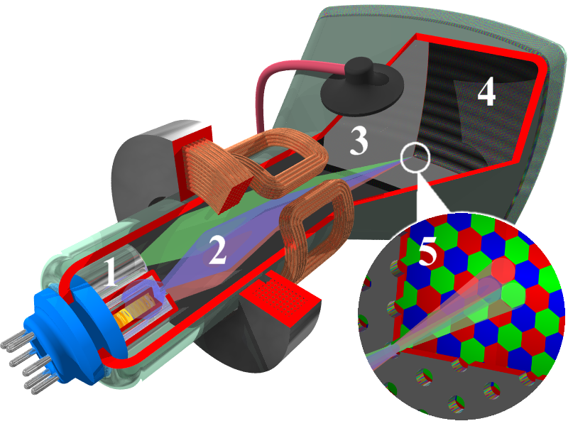
The tube, basically consists of an electron gun, cathode, which shoots electrons at the screen, anode. The stream of electrons is first focused and then bent using electromagnets to deflect the electrons toward different parts of the screen. At the screen, the stream of electrons strikes a phosphor which glows. The intensity of the glow is determined by the number of electrons striking each dot. If we are discussing a color CRT, we are talking about three guns, one for each primary color. Due to the small size of the phosphor dots our eye blends the three color dots into a single colored pixel.
Here in the US the older CRTs refreshed at 30 frames per second, using an interlaced pattern. Newer CRTs though, use a non-interlaced pattern and so they can refresh at 60 times per second, or higher.
LCD
As more and more people turn desktop computers to laptop computer, there is a move from the CRT display to the LCD display.
Some people prefer the LCD since it is lighter and slimmer. I tend to still prefer the CRT to the LCD, because of the sharpness and it’s ability to deal with moving images. But it seems I am in the minority these days.
Lets take a look at how the LCD display works.
A simple black - or - white LCD display works by either allowing daylight to be reflected back out at the viewer or preventing it from doing so - in which case the viewer sees a black area. The liquid crystal is the part of the system that either prevents light from passing through it or not.
The crystal is placed between two polarising filters that are at right angles to each other and together block light. When there is no electric current applied to the crystal, it twists light by 90o, which allows the light to pass through the second polariser and be reflected back. But when the voltage is applied, the crystal molecules align themselves, and light cannot pass through the polariser: the segment turns black.
Selective application of voltage to electrode segments creates the digits we see.
Printers
The common way of creating hard copy from a computer is to use a printer. Now printers come in many different varieties. In this section we will review the Dot Matrix, the Inkjet, and the Laser printer since these are the most common. The printer types we will not review are line printers, chain printers, thermal transfer printers, dye transfer, selectric printers, and photo lithography.
Dot Matrix printer
For many years the Dot Matrix Printer was the print technology of choice. The mechanism was simple and dependable. The basic idea was the same as that used in the typewriter.
Here is a good picture which explains how the print head works.
And if that was not fun enough, here is a animated picture which demonstrated how to create type with the pins in a print head.

Inkjet Printers
The Inkjet Printer is a common type of printer which works by spraying a tiny drop of ink at paper. The technology is probably best explained by this animated picture.

The printing works the same way as the dot matrix print head above. The only difference is that we are now using droplets of ink instead of hammers.
Laser Printer
The Laser Printer has become so common that most of us take it for granted. The reason for it’s success can be attributed to it’s simplicity, durability, and inexpensive toner. I think the best explanations come from pictures, so here are a few.
First lets look at how this type of printer works.
Now lets look at how the laser writes on the drum.
Finally lets look at the difference between the printing method used by inkjet and the laser.

Sound
I don’t know about you, but lately, I find myself listening to music more often than printing lately. I don’t know if I am unusual or not but I find computer music very appealing due to it’s convenience.
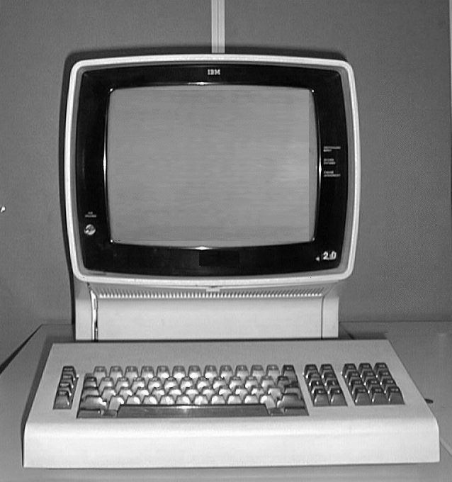
Sound on the IBM PC (1981) originally meant what ever sound you could generate from the internal speaker and it’s controller chip. Lets play a sample of the type of sounds that were created by that speaker for games. Monkey Island (mp3)
Of course with some clever programming people were able to get better sounds from that little speaker. Here is a sample of music created and played through a PC speaker. Mushroom Air Freshener (mp3)
By about 1987, IBM and Yamaha came out with a sound card for the PC. It was basically a Yamaha synthesizer on a PC card. This came after the Adlib card, but it also included a library of sounds. Colonel’s Bequest (mp3)
Starting in 1989, and again in 1991, the Sound Blaster cards came on the market. They were a little sloppy at first, but were cheaper than the current cards. They brought a whole new level of music to the PC as seen here, Epic Pinball (mp3)
Lastly, as least for now, Creative came out with the AWE32 board in 1993. It added both a synthesizer chip and an encoding chip to the board. You could now record CD quality sound as well as play full Midi files on your sound card. So we can now listen to a better version of Monkey Island (mp3) as it would sound from the Sound Blaster AWE32 board.
Now Sound on the PC is a whole topic by itself. I will not expand on it any more for now, but in the future I hope to do a whole presentation on Music under Linux. For those of you who would like to know more about computer sound I recommend Phonomenal! … a retrospective view on sound card history
Storage Devices
Data storage is a major concern on any computer. The storage and retrieval of information takes many forms in computers. Here are a few of the most common technologies.
Floppy Disk
One of the first long term storage devices on the PC was the Floppy Disk. I have always been fascinated that people often do not connect the floppy disk with the Cassette tape used for music.
The disk in a floppy consists of a magnetic oxide sandwiched between layers of plastic. The magnetic particles are magnetized using an electromagnet in the head. This head can both read and write the magnetic fields on the medium. This is the same mechanism used by a hard disk, a zip disk or a tape drive.
The original floppies were 8 inches in diameter developed by IBM. The next generation were the 5 1/4 inch size. The original PC came with 2 360 Kilobyte 5 1/4 inch drives. Later they developed the 3 1/2 inch floppy with a harder case to protect the medium better.
The floppy is generally controlled by a chip on the mother board. It uses a ribbon cable to connect the drive to the motherboard. Typically the cable has a connector which is keyed. But if the connector is not keyed, look for the side of the ribbon cable which is colored, that is the pin 1 side of the connector. Usually the connectors on the motherboard are labeled, as well is the connector on the floppy drive.
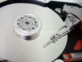
Hard Disk
The Hard Disk hardly needs any introduction to this group. This is the primary means of storage on most PCs these days. They are fast, cheap, and dependable.
The technology used here is the same as the floppy disk, with a couple of exceptions. In the floppy drive, the head actually rests on the media, while the hard disk, it flies above the medium. The other obvious difference is the floppy is a flexible medium, while the hard disk is a rigid backing. Finally, most hard disk contain multiple platters while a floppy only contains a single platter.
One issue with a hard disk is the type of controller it needs. Here is a quote from Wikipedia which explains it well.
A hard disk is generally accessed over one of a number of bus types, including ATA (IDE, EIDE), Serial ATA, SCSI, SAS, FireWire (aka IEEE 1394), USB, and Fibre Channel.
Back in the days of the ST-506 interface, the data encoding scheme was also important. The first ST-506 disks used Modified Frequency Modulation (MFM) encoding (which is still used on the common “1.44 MB” (1.4 MiB) 3.5-inch floppy), and ran at a data rate of 5 megabits per second. Later on, controllers using 2,7 RLL (or just “RLL”) encoding increased this by half, to 7.5 megabits per second; it also increased drive capacity by half.
Many ST-506 interface drives were only certified by the manufacturer to run at the lower MFM data rate, while other models (usually more expensive versions of the same basic drive) were certified to run at the higher RLL data rate. In some cases, the drive was over engineered just enough to allow the MFM-certified model to run at the faster data rate; however, this was often unreliable and was not recommended. (An RLL-certified drive could run on a MFM controller, but with 1/3 less data capacity and speed.)
ESDI also supported multiple data rates (ESDI drives always used 2,7 RLL, but at 10, 15 or 20 megabits per second), but this was usually negotiated automatically by the drive and controller; most of the time, however, 15 or 20 megabit ESDI drives weren’t downward compatible (i.e. a 15 or 20 megabit drive wouldn’t run on a 10 megabit controller). ESDI drives typically also had jumpers to set the number of sectors per track and (in some cases) sector size.
SCSI originally had just one speed, 5 MHz (for a maximum data rate of 5 megabytes per second), but later this was increased dramatically. The SCSI bus speed had no bearing on the drive’s internal speed because of buffering between the SCSI bus and the drive’s internal data bus; however, many early drives had very small buffers, and thus had to be reformatted to a different interleave (just like ST-506 drives) when used on slow computers, such as early IBM PC compatibles and Apple Macintoshes.
ATA drives have typically had no problems with interleave or data rate, due to their controller design, but many early models were incompatible with each other and couldn’t run in a master/slave setup (two drives on the same cable). This was mostly remedied by the mid-1990s, when ATA’s specification was standardized and the details begun to be cleaned up, but still causes problems occasionally (especially with CD-ROM and DVD-ROM drives, and when mixing Ultra DMA and non-UDMA devices).
Serial ATA does away with master/slave setups entirely, placing each drive on its own channel (with its own set of I/O ports) instead.
FireWire/IEEE 1394 and USB(1.0/2.0) hard disks are external units containing generally ATA or SCSI drives with ports on the back allowing very simple and effective expansion and mobility. Most FireWire/IEEE 1394 models are able to daisy-chain in order to continue adding peripherals without requiring additional ports on the computer itself.
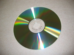
CD-Rom
The CD-Rom is similar to the audio CD. The use of the CD has revolutionized data distribution on the PC due to it’s size and cost.
There are three common types of CDs, those pressed, those burned, and those burned and erased. Here is a discussion of how the CD-R works.
A CD-R (Compact Disk Recordable) is a special type of CD which is coated with a photosensitive organic dye which allows a user to record information to a special type of cd for backup and duplication purposes. Once the CD-R disk is placed within the computer the recording process begins the laser heats and the dye reveals the areas to diffuse light just as a regular CD would. The CD-R drive does not actually create pits on the CD instead the burner creates reflective sections on the CD causing the computers CD-ROM laser to interpret it as a pit. Because of this method of creating a CD, CD-R drives are only capable of recording to the CD once. This unfortunately means if you encounter errors or do not complete the recording process the CD may become useless.
The CD-rom drives normally interface using the same standards and cable used for the Hard disk.
DVD
This relative of the CD-Rom was created originally to display movies in the home. Since then the computer industry has adopted this format due to it’s large capacity.
DVD (Digital Versatile Disc or Digital Video Disc) - Is the new future of computer CD-ROM drives. DVD drives became a new computer standard September of 1995 with several various organizations decided upon it. The DVD technology allows for 4.7G of storage space compared to the 650MB of storage space of the conventional CD-ROM drive.
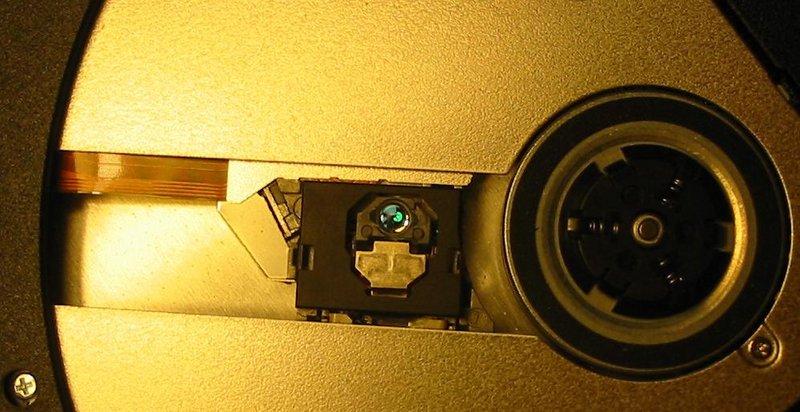
The DVD technology is very different from the technology used in standard CD-ROM drives. DVD uses shorter wavelength lasers to read smaller pits and lands. Discs also have two layers the first layer is semi-reflective to allow the laser to penetrate it and get to the substance beneath it. This allows one side of the DVD to have twice the capacity. Also DVD has the capability of doubling its original capacity by using both sides of the disc. DVD drives also spin at a base speed that is about three times as fast as a single speed CD-ROM drive.
The DVD drive connects to the same cables as the hard disk drive. Here is what the inside of a DVD drives looks like.
Tape Drive
Tape drives are a fairly old storage medium. Their cost is low relative to the amount of data they can store. These serial devices have been used for a long time by business.
TAPE DRIVE STANDARDS
8mm Tape Drive - Manufactured and available through Exabyte. 8mm tapes are similar to what are used in camcorder. 8mm tapes are a faster solution then the DAT and transfer up to 6M/Sec. While the tapes are similar to camcorder tapes it is recommended that to backup information you use 8mm tapes designed for your drive.
DAT (Digital Audio Tape) - Please see our DAT dictionary definition page for additional information about this standard.
DLT (Digital Linear Tape) - DLT drives are a robust and durable medium. The DLT segments the tape into parallel horizontal tracks and records data by streaming the tape across a single stationary head. Released in 1991 DLT drives are very reliable, high-speed, and high-capacity making the DLT drives an excellent use for Network backups.
QIC Standard - Please see our QIC dictionary definition page for additional information about this standard.
The interface for the tape drive is often a dedicated port. This is because, other than SCSI, most hard drive controllers can not deal with tape drives.
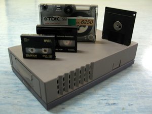
Memory Card
Today Flash Memory, has largely taken the place of the Floppy Disk. This is good and bad, the memory stick has a shorter life for writing to than the floppy drive. The plus side is that it is larger and faster than the floppy disk.
I am using the term memory card to include a number of different devices and technologies. These include Smart Media, Secure Digital, Multimedia Card, Memory Stick, CompactFlash, and USB Flash Memory.
The ideas is that all these technologies are designed to plug into the computer and transfer data.
Reference
That is all we are going to cover in this meeting. If you have more questions we can discuss them at another time. If you have specific items you would like added to this presentation, please let me know and I will see what I can do.
In the process of researching this presentation I came across an interesting book on line of PC architecture. Have a look at: PC Architecture Additionally I found the web site: Computer Hope’s free computer help
Written by John F. Moore
Last Revised: Tue 01 Sep 2020 08:10:08 PM EDT

This work is licensed under a Creative Commons Attribution-NonCommercial-ShareAlike 3.0 Unported License.