Abstract
So you decided to build you very own CNC (Computer Numeric Control) router. Now you need software to control the CNC. You need a design program to create your master pieces. You need to convert your master piece for the CNC control software. Linux comes to the rescue. Come along for an interesting walk throught wood working Linux style.
DIY CNC
So you have done some word working, mostly not too complex, but you fee up to a challenge. You just happen to be reasonably competent with computer hardware. Now let see what interesting project we can come up with.
Build Your CNC
In the process of researching what project you want to do you come across an interesting web site with a book about DIY CNC. So you figure you will take a look and buy the book for your Kindle. Kindle Book under Chrome
After reviewing the information you figure you can handle the wood working given all the available documentation. You have most of the wood working tools, but you add a few bits to your collection.
Next you need to get the mechanical parts that are not wood working such as Bearings, Thread Rod, and finally CNC Motor Kit. There is also things like nuts and bolts, and angle iron, but that is available from a local hardware store.
In the process of building the cnc it is interesting to watch some of the many YouTube DIY CNC videos to learn different ways of build your machine. I mean after all it is your project, so revising parts of it during the build process is part of the fun.
Wiring Your CNC
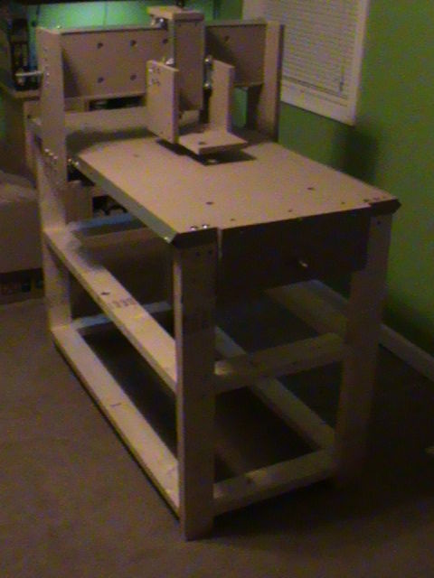
Once you have completed the basic machine, you need to wire it. Yes there are tutorials on how to hook up the wires. But those are general ideas, you need to figure out exactly how to implement them.
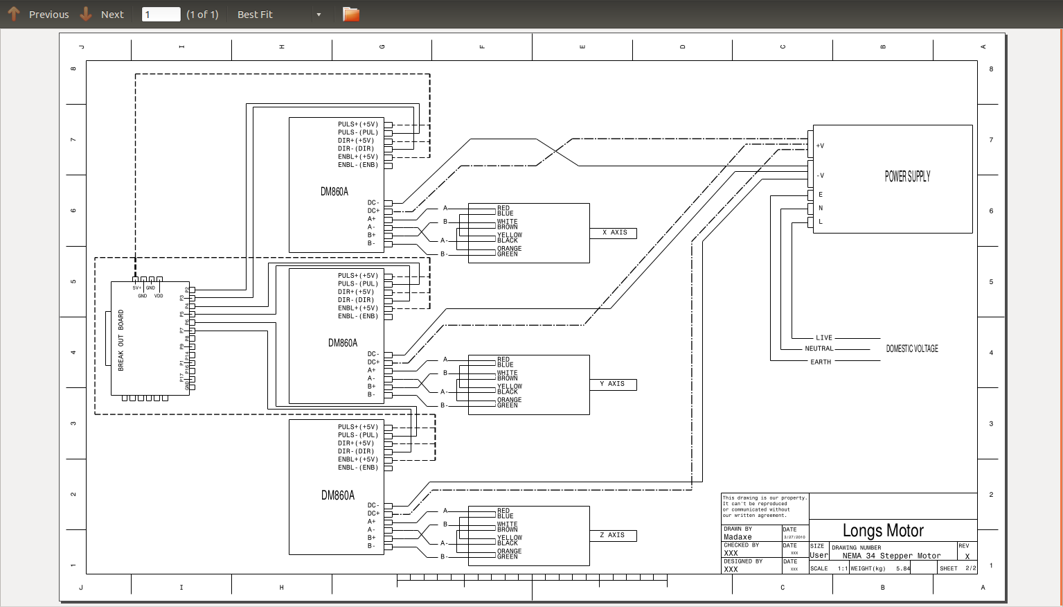
There are some writing diagrams like this one from Longs Motor which leaves out the 5 Volt supply needed. Besides it is missing the wiring for the limit switches.
Lastly, but not least you need the wiring for things like an Emergency Stop switch, power for the stepper motors, and power for the router. These things are suggested by more reading, so I tried to put together the best of all the reading into a finished piece.
Lastly, since the is Computer Numeric Control, you need a computer and some place to put it. One requirement is a parallel port. Now in the past these were common for driving printers. Today they are less common since everything uses USB ports. But it is a great use for an older desktop computer since you don’t need a lot of processing power. After all this is an instrument controller not a general purpose computer.
Linux for you CNC
So now that you have the physical machine you need software to control the motors. Well as I am fond of saying LinuxCNC comes to your rescue. The authors have already done the work of creating a piece of software to drive your new device.
The program takes instructions in a format known as G-code which instruction the three motors how to move. Not only are the instructions sent to the motors, but it includes a graph showing you what it is doing during the processing.
One trip point though is the configuration you need to do to match your hardware to the software. This takes some understanding of the hardware and some trial and error to get it right. In the end I got information from several sources and experimented to find the best balance between speed and accuracy.
To be honest, there were decisions made during the whole process which affect how the final machine is built. For example, you have the number of steps each motor needs for a full revolution. Then you have to make a decision about the number of turns per inch your thread rod will use. Lastly, you will need to decide how many micro steps you want for each step. Now before your eyes glaze over too much, there is a lot of help on the internet.
How does a CNC Router Work?
Before I start to describe the tools and methods using in creating objects with a CNC router, lets see if I can give you a visual picture of how the tool works.
Imagine you have a piece of paper in front of you and a felt tip marker in your hand, and you are makeing a sign that says “I (Heart) Linux”. First you pick a starting point on the page for the capital I. You put the tip of the felt tip on the paper and draw the top of the capital I. Next you pick up your pen and move to the middle of the top of the capital I and put down your pen. Move the pen down to the bottom of the capital I. Pick up your pen and move to the start of the cross bar at the foot of the capital I. Put the pen down, and draw a line for the bottom. Pick up your pen, move to the center of the heart, put your pend down. Draw one side of the heart. ETC. By now you get the picture, I hope.
Describing this in steps might seem tedious, but that is how a robot is programmed, which is how a CNC works.
The starting point is known as the origin and is designated as X0, Y0, and Z0. X being the table front to back movement, Y is the left and right movement, and Z moves the router up and down. With this combination of three axis you can move the router where ever you wish on the table surface.
This is the action or a router in a CNC Router. It is also how a 3D printer works. A 3D printer moves to a location on the table, and spits out a drop of plastic, or what ever material is being deposited. So if you have a CNC Router, you already have 90% of a 3D printer, you just replace the router with a plastic injector, and hook up a wire to control the depositor.
Engrave or 3D Design
The CNC router is a subtractive tool. This means that you start with a block of some material, usually wood, and cut away the excess to create your object. This is just opposite of a 3D printer. In a printer you are going to use an additive process to create something.
The CNC Router, can be used to do either engraving work or 3D design.
The difference between 2D, 2.5D and 3D is how the router does it’s cutting. When the CNC Router is used for engraving, the movement of the X and Y axis smoothly move the cutting head as though it were a drawing pen.
When we talk about 3D, typically we are moving all 3 axis at once to create depth like a relief or a shape. In 3D the cutting head will sweep back and forth across the work removing layers of material.
CNC Language
Before we discuss how to create objects for the CNC, lets take a minute and discuss what language the LinuxCNC tool uses. The language is called G code, which is for all CNC machines. It is an interperted language directing the three or more motors.
You can find a reasonable tutorial at LinuxCNC G Code Tutorial.
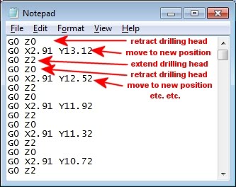
Before we look at how to design your creations, lets have a look at a sample of G-Code to see how it works. You could actually write your creations in G-code directly, but that would be like writing your computer programs in assembly code. In addition to having an understanding of G-code, this will help you understand how a CNC Router works.
How to Create new Things
We have talked about how to build the CNC Router, now lets talk about how you would go about making something. First we will talk about how to go from an Idea to a finished product. Then we will discuss the tools you need to get the job done.
First Design
As with any design you start with an idea, and typically will do a drawing or sketch to begin. This is the brain storming part of the process which often only needs a pencil and paper.
At this stage you make the high level decisions of what you want to build, and how you envision it. At this point the only limitation is your imagination.
There is more that brain storming at this point, you need to decide about how you want to approach the project. For example if you are designing a chair, you might spend some time thinking about how you are going to assemble the pieces, unless you have a VERY big machine which could cut it out of a single block of wood.
Design planning
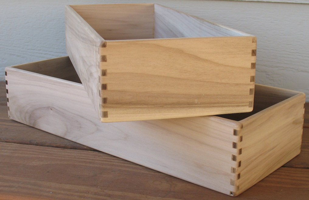
Let me give you a simple example of what I am talking about. Suppose you want to make a box. Lets assume it will be simple with only 4 sides and a bottom.
So you sketch it out on paper, then you might use a CAD program to lay it out. Looks good for now.
But to make it you are going to need to cut out the 4 sides separately. You will also need to think about how the sides are joined to each other. Lets look at a simple box to see how it was put together.
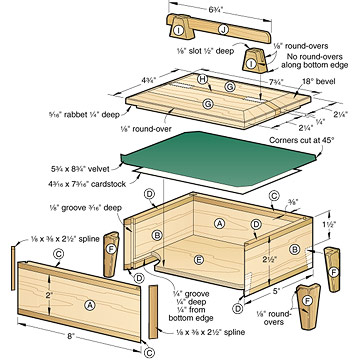
This gives you some idea of what ideas are needed. As a further example lets look an exploded view of a box.
OK now that I have scared you, lets talk about a much simplier use for your CNC Router.
Engraving
Lets start at the beginning with engraving. I am going to start with engraving since it is simplier to create signs. The learning curve is simplier, and the application F-Engrave is much easier to use. Besides, it generates G-Code directly so no conversion is needed.
Typically you decide on what text or art you want to engrave. Then you fire up a program and start the design. You decide on a font, decide what you want it to say, lay out the words in a pleasing manner, and generate your G-Code.
Rather than me trying to explain this lets have a look at a youtube video from the author of F-Engrave.
|
V0.1 F-Engrave video manual |
Designing 3D
Written by John F. Moore
Last Revised: Tue 01 Sep 2020 08:10:08 PM EDT

This work is licensed under a Creative Commons Attribution-NonCommercial-ShareAlike 3.0 Unported License.